Jump to a section:
Basic Operation:
Advanced Nintendo 64 Controller Settings:
Advanced GameCube Controller Settings:
Advanced Operation:
Basic Operation
Choosing a Mapping
Whenever you start a game, you must ensure that you select the correct mapping for your game. If you play with the incorrect mapping chosen, the
buttons and/or analogue stick will me incorrectly mapped, and will not function as intended.
Selecting a mapping is simple. First ensure that a controller is connected, the adapter is plugged into the Wii / GameCube, and the console is
switched on. The LED should be illuminated. Next, hold down the following buttons on the Nintendo 64 controller:

Or the following buttons on the GameCube controller:

Now press up or down on the D-pad to cycle through the 8 different mappings. The LED will change colour to display the currently selected
mapping.
The LED colour indicates the currently selected mapping. In order to determine the correct mapping for your game, you can use the
mapping table below. A scaled-down version of the same mapping table is also printed on the front of the adapter, so you don't need to
look up the table every time you change the game!
When you power off the console or unplug the adapter, the current mapping is saved. So the next time you play, the previously used mapping will be loaded automatically.
Mapping Table
| Platform | Game | Mapping |
|---|---|---|
| Wii VC | Super Mario 64 | Red |
| Wii VC | Mario Kart 64 | Red |
| Wii VC | The Legend of Zelda: Ocarina of Time | Dark Blue |
| Wii VC | Star Fox 64 | Light Blue |
| Wii VC | F-Zero X | Purple |
| Wii VC | Paper Mario | Light Blue |
| Wii VC | Wave Race 64 | Light Blue |
| Wii VC | Yoshi's Story | Light Blue |
| Wii VC | Sin and Punishment | Orange |
| Wii VC | Pokémon Snap | Light Blue |
| Wii VC | 1080° Snowboarding | Light Blue |
| Wii VC | Kirby 64: The Crystal Shards | Yellow |
| Wii VC | Cruis'n USA | Light Blue |
| Wii VC | Pokémon Puzzle League | Yellow |
| Wii VC | Mario Golf | Light Blue |
| Wii VC | The Legend of Zelda: Majora's Mask | Purple |
| Wii VC | Super Smash Bros. | Light Blue |
| Wii VC | Ogre Battle 64: Person of Lordly Caliber | Light Blue |
| Wii VC | Mario Tennis | Light Blue |
| Wii VC | Mario Party 2 | Light Blue |
| Wii VC | Bomberman Hero | Light Blue |
| GameCube | The Legend of Zelda: Ocarina of Time & Master Quest | Green |
| GameCube | The Legend of Zelda: Collector's Edition | Green |
| GameCube | Other GameCube Games | White |
| Other | Other (generic) use | White |
Please note: There are multiple versions of the Legend of Zelda: Ocarina of Time, and Majora's Mask! These are the Wii Virtual Console versions, and the GameCube versions. These versions use different mappings, so make sure that you choose the correct mapping for the version you are playing!
Advanced Nintendo 64 Controller Settings
Generic Mapping (white LED)
Please Note: This mapping should NOT be used when playing a game listed in the mapping table above! This mapping should only be used when playing original GameCube releases with a Nintendo 64 controller.
In order to give the player the full functionality of a GameCube controller when using a Nintendo 64 controller... the white mapping lets you change the
functionality of the C-buttons depending on whether-or-not the L-button is held down.
The C-buttons can be either mapped to the GameCube C-stick, or the X, Y and Z buttons.
By default, the C-buttons are mapped to the X, Y and Z buttons, and when the L-button is held, they are mapped to the C-stick. However, when
alternate button mode is enabled, this functionality is reversed... meaning they are mapped to the C-stick by default, and when
the L-button is held, they are mapped to the X, Y and Z buttons. So if you are playing a game which predominantly uses the C-stick, you should use
alternate button mode, to reduce the need to hold down the L-button all the time.
The L-button has another feature. When the L-button is held, Z and R will act as reduced presses of the GameCube L and R
triggers, rather than full presses which is the default. This allows slightly more control when using the adapter to play GameCube games.
The graphic below more clealy shows how the C-buttons are mapped when using the white mapping:
")
Alternate Button Mode (flashing LED)
Alternate Button mode performs a very specific function, and is not required for normal operation. It is only available for three mappings (white,
Alternate Button Mode is on if the LED is flashing. If your adapter has dual-inputs, the flashing will instead indicate alternate button mode only if a Nintendo 64 controller is connected, otherwise it will indicate the trigger mode.
If the currently selected mapping supports alternate button mode, toggling alternate button mode is simple. First ensure that a Nintendo 64 controller is connected, the adapter is plugged
into the Wii / GameCube, and the console is switched on. The LED should be illuminated. Next, hold down the following buttons on the Nintendo 64 controller:
Now press right on the D-pad to toggle alternate button mode. The LED will either start or stop flashing to indicate whether alternate button mode is enabled or disabled.
Alternate Button mode for the white mapping is explained under the "Generic Mapping" section.
For the
For the
As with the mapping, the trigger mode is saved, and restored automatically for when the console is powered off. Changing the mapping will automatically disable alternate button mode.
Advanced GameCube Controller Settings
GameCube to N64 Stick Mapping
In order to pass the GameCube controller's stick values through the same inverse mapping function as the Nintendo 64 stick values, they must first be warped to fit within the full working range of a Nintendo 64 controller's analogue stick. There are two built-in GameCube to Nintendo 64 stick mappings built into the adapter. These are my own custom mapping, and a mapping identical to the Raphnet version 2.0 mapping.
You can find a more in-depth explanation of the two mappings, including before and after plots of each of the two here. I recommend using my mapping, but, I've added the option for people who are familiar with the Raphnet version 2.0 mapping. It will make playing on Wii VC feel just like playing on the Nintendo 64 with the GameCube to N64 Raphnet adapter (version 2.0).
In order to change the mapping, simply toggle the switch on the side of the adapter. If the switch flipped to the right (towards the outside), then you are using my stick mapping. If the switch is flipped to the left (towards the inside), then you are using the Raphnet adapter mapping.

Trigger Modes
There are three different trigger modes available:
-
Normal triggers
Soft triggers
Hard triggers
"Normal triggers" mode will leave the triggers unaltered. They will act the same as they do normally.
"Soft triggers" mode will threshold the analogue trigger values for L and R at around 60. Anything higher than this will act as a full (digital) trigger press in-game. This is useful for example if you prefer the "soft" triggers, like in the GameCube rereleases of the Legend of Zelda OOT, MM and MQ, and want those style triggers when playing the Wii Virtual Console versions.
"Hard triggers" mode will set the analogue trigger values for L and R to zero, unless the triggers are fully depressed (digitally), in which case they will be set to 255. This is useful for example if you prefer the "hard" triggers, like in the Wii Virtual Console rereleases of the Legend of Zelda OOT and MM, and want those style triggers when playing the GameCube versions.
If you have a single-input GameCube adapter, or a dual input adapter which is using the GameCube controller input (ie, only a GameCube controller is connected), then the flashing of the LED will tell you that a forced trigger mode is being used (either "soft" or "hard"). If a Nintendo 64 controller is connected however, the flashing will that indicate alternate button mode is enabled, so please be aware of this.
If the LED is flashing, there is no indication which of the soft or hard trigger modes is being used. You can tell by either depressing the triggers to find out, or by cycling through the 3 modes to get to whichever mode you want.
Changing the trigger mode is done in a similar way to toggling alternate button mode, but with a GameCube controller. First, you must hold down the following buttons on the GameCube controller:
Now press right on the D-pad. This will cycle through the three trigger modes in the order of "normal", "soft", "hard". If no N64 controller is connected, then the LED may either start or stop flashing to indicate whether you are using a forced trigger mode or not.
As with alternate button mode, the trigger mode is saved, and restored automatically for when the console is powered off. Changing the mapping will reset the trigger mode back to "normal triggers" mode.
Advanced Operation
Input Display Feature
Firstly, please ensure you know what you are doing before connecting anything to the adapter! Connecting something incorrectly could potentially damage your adapter! Please note that I cannot be held responsible for any damage caused, or problems that may
arise due to incorrect use of the input display feature. Having said that, there are only two connections, and as long as the adapter is set to 3.3V, it should be basically impossible for you to do any damage.
In order to use the input display feature, you will need a separate USB to UART / Serial converter and two jumper wires. You can either order one with your adapter... or you can buy them separately yourself. See here for more information about what to buy.
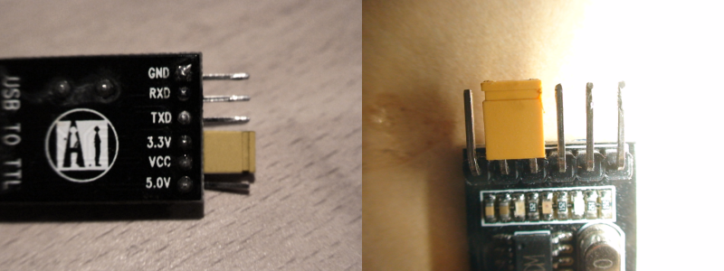
Before you connect anything, first ensure that your USB to UART / Serial converter is set to 3.3V. This is usually done by connecting a jumper between the pin labelled "Vcc" and the pin labelled "3.3V".
Like so:
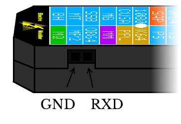
The two sockets on the side of the adapter are for the input display. The one closest to the edge is Gnd, and the one closest to the middle is RXD. Connect these to the corresponding pins on your USB to UART / Serial converter, like so:
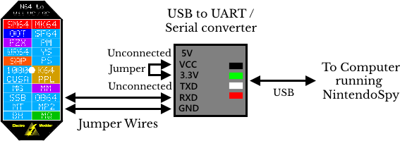
This is designed to work with the "NintendoSpy" software. Make sure you select the correct COM port in the software, and you choose the correct one of "Nintendo 64" or "GameCube" under "Controller Source".
One thing to be aware of is that the jumper wires which come with the adapter are very short (rougly 8 inches long). You might want to also invest in a cheap USB extension cable if you don't already have one.
A known bug when connecting this converter (and similar converters) is that your OS might incorrectly detect it as a serial mouse. This will cause your cursor to "glitch out" and jump around. This problem can be avoided if NintendoSpy is open before you connect the adapter, or switch on the Wii. Alternatively, if this continues to be a problem... you can disable serial mouse auto-detection - see here for more information.
If you have attemped the steps above, but are having problems getting it to work... please feel free to contact me at support@electromodder.co.uk and I will do my best to help.
What to buy?
If you choose to buy a serial converter yourself rather than using the one which comes with the adapter, they can be bought for about £1 on Ebay. You MUST
get one which works at 3.3V... many have the option to work at either 5V or 3.3V, these will do fine. Any which have "CH340G" in the title should work.
For reference, the one which comes with the adapter is the following model:
Adapter Link 1
Adapter Link 2
Adapter Link 3
Adapter Link 4
Your adapter will have a female header, so ensure that your USB to UART converter has male headers like the model above, or that you buy some male to male 2.54mm pitch connectors, or jumper/breadboard cables, so you can connect them together.
For the adapter above, you can either bend the extra pins out of the way so the RXD and Gnd pins fit directly into the adapter... or alternatively you can use two male to female 2.54mm pitch jumper wires. These can be
easily found on Ebay, and are often listed as "breadboard" wires. Here are a few links to some wires which should work:
Jumper Wires Link 1
Jumper Wires Link 2
Jumper Wires Link 3
Jumper Wires Link 4
If you buy a converter with a USB port soldered directly onto the board like the one above, rather than a cable, you might also want to buy a USB extension cable. Otherwise, you will need to have the adapter very close to your computer when using the input display feature.